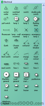
Visio Electrical Engineering Shapes Free Download
Use the Electrical Engineering drawing type to create electrical and electronic schematic diagrams.
Aug 04, 2017 Does Visio 2007 automatically have electrical shapes installed? I was instructed: 'To create Electrical diagrams in Visio 2007, please review the following article titled “Create an electrical. Use Visio to create electrical engineering diagrams, including basic electrical, circuits and logic, systems, and more.

On the File tab, click New, and then search for Engineering templates.
Click one of the following:
Basic Electrical
Circuits and Logic
Fluid Power
Industrial Control Systems
Parts and Assembly Drawing
Piping and Instrumentation Design
Plumbing and Piping Plan
Process Flow Diagram
Systems
TQM diagram
Work Flow Diagram
Choose Metric Units or US Units, and then click Create.
The template opens an unscaled drawing page in portrait orientation . You can change these settings at any time.
Drag electrical component shapes onto the drawing page. Shapes can have data. You can enter shape data and add new data to a shape.
Enter shape data
Select a shape, right-click, click Data, and then click Define Shape Data.
In the Define Shape Data dialog box, click in each item and type or select a value.
Use the Connector tool to connect electrical components or connector shapes.
Use the Connector tool
Click the Connector tool .
Drag from a connection point on the first shape to a connection point on the second shape. The connector endpoints turn red when the shapes are connected.
Use connector shapes
Drag a connector shape onto the drawing page.
George harrison discography beatles. Place the connector's begin point on the parent shape (the shape you’re connecting from).
Place the connector's end point on the child shape (the shape you’re connecting to).
When the connector is glued to the shapes, the endpoints turn red.
Label individual electrical component shapes by selecting the shape and typing.

On the File tab, click New, and then under Template Categories, click Engineering.
Click one of the following:
Basic Electrical
Circuits and Logic
Fluid Power
Industrial Control Systems
Parts and Assembly Drawing
Piping and Instrumentation Design
Process Flow Diagram
Systems
Choose Metric Units or US Units, and then click Create.
The template opens an unscaled drawing page in portrait orientation . You can change these settings at any time.
Drag electrical component shapes onto the drawing page. Shapes can have data. You can enter shape data and add new data to a shape.
Enter shape data
Select a shape, right-click, click Data, and then click Define Shape Data.
In the Define Shape Data dialog box, click in each item and type or select a value.
Connect electrical components using the Connector tool or connector shapes.
Use the Connector tool
Click the Connector tool .
Drag from a connection point on the first shape to a connection point on the second shape. The connector endpoints turn red when the shapes are connected.
Use connector shapes
Drag a connector shape onto the drawing page.
Place the connector's begin point on the parent shape (the shape you’re connecting from).
Place the connector's end point on the child shape (the shape you’re connecting to).
When the connector is glued to the shapes, the endpoints turn red.
Label individual electrical component shapes by selecting the shape and typing.
On the File menu, point to New, point to Engineering, and then click one of the following:
Basic Electrical
Circuits and Logic
Industrial Control Systems
Systems
These templates open an unscaled drawing page in portrait orientation . You can change these settings at any time.
Drag electrical component shapes onto the drawing page. Shapes can have data. You can enter shape data and add new data to a shape.
Check out Lament (Cinematic/Celtic Version) by Light of Aidan on Amazon Music. Stream ad-free. Buy song $0.89 Add to MP3 Cart Song in MP3 cart. Free download Lament - light of aidan - Trailer Song Halo ODST #4258141 mp3. Did you like the song? Light of AidanLament (Cinematic Celtic Version). Free download Light of Aidan - Lament (Cinematic Celtic Version) #4258166 mp3 or listen online music. Light of aidan lament cinematic celtic version mp3 download. Free download Light of Aidan - Lament #4258165 mp3 or listen online music. Did you like the song? Light of AidanLament (Cinematic Celtic Version).
Enter shape data
Select a shape, and then on the Shape menu, click Shape Data.
In the Shape Data dialog box, click in each item and type or select a value.
Connect electrical components using the Connector tool or connector shapes.
So it is important to save these emails for all time. If you bought Movie Studio from Magix and activated the program, you should be able to find your activation codes in your Magix account. Movie studio platinum 13 0 serial number. Or Did you buy from another store like Amazon? When you buy software from any store online as a download, they always email you your Serial Activation codes.
Use the Connector tool
Click the Connector tool .
Drag from a connection point on the first shape to a connection point on the second shape. The connector endpoints turn red when the shapes are connected.
Use connector shapes
Drag a connector shape onto the drawing page.
Place the connector's begin point on the parent shape (the shape you’re connecting from).
Place the connector's end point on the child shape (the shape you’re connecting to).
When the connector is glued to the shapes, the endpoints turn red.
Label individual electrical component shapes by selecting the shape and typing.